

How to Plan Gym Equipment Installation for Your Facility
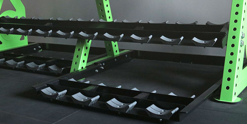
Many facility operators treat equipment arrival as the final step of a project, only to realize too late that the heavy machinery doesn't fit through the service elevator or the floor cannot support the localized point load of a heavy power rack. This oversight leads to catastrophic delays, increased shipping returns, and skyrocketing labor costs. A successful installation is not merely a matter of unboxing; it is a rigorous logistical orchestration that begins months before the first crate arrives.
Addressing the Fallacy of Instant Setup Readiness
A common misconception in facility management is that once the floor is polished and the walls are painted, the space is ready for assembly. In reality, the most expensive errors occur in the gap between structural readiness and equipment compatibility. If you haven't verified the load-bearing capacity of your subfloor or the clearance required for a cable machine's full range of motion, your installation is destined for failure.
We often see operators purchasing high-end cardio equipment only to find the electrical outlet is six inches too far from the intended cord length, or that the ceiling height prevents the full extension of a functional trainer. This isn't just an inconvenience; it is a failure of pre-installation planning. Before we look at the physical movement of goods, we must establish the technical baseline of your environment.
Establishing Site Tolerance and Structural Integrity
Before any heavy lifting begins, you must move from a general sense of "space availability" to precise measurement of site tolerances. A gym floor is not just a flat surface; it is a structural component that must interact with the equipment's footprint.
Verifying Floor Load-Bearing Capacity
The primary cause of structural fatigue in commercial gyms is localized weight concentration. A single heavy dumbbell rack or a multi-station strength machine exerts much higher pressure than a standard human footprint. You must consult your structural engineer to determine the maximum PSI (pounds per square inch) your floor can handle.
- Static Load: The constant weight of the machines themselves.
- Dynamic Load: The temporary, high-impact force generated by users (e.g., dropping a barbell or jumping on a plyo box).
- Verification: Request a formal load-bearing spec sheet from your building's management to ensure your equipment density doesn't exceed the structural limit.
It is a mistake to measure only the machine's footprint. You must account for the "operational envelope"—the total space a machine occupies during its maximum range of motion. A cable crossover machine might have a small base, but its arms expand significantly during use.
| Equipment Type | Critical Dimension to Measure | Common Error |
|---|---|---|
| Cable Machines | Maximum Arm Spread & Height | Ignoring ceiling height for top pulleys |
| Power Racks | Barbell Length + Clearance | Placing too close to walls/pillars |
| Treadmills | Rear Safety Clearance | Insufficient space behind the machine |
| Selectorized Strength | Weight Stack Verticality | Ignoring the space needed for weight changes |
Once you have verified that the physical environment can support the weight and dimensions of your inventory, the focus shifts toward the logistical movement of these items into the facility.
Explore the complete technical specifications:
Optimizing the Logistics and Delivery Path
Even the best-planned layout fails if the equipment cannot physically reach the designated area. A highly frequent failure mode is the "narrow doorway bottleneck," where a large piece of equipment is undamaged but simply cannot pass through the service entrance or hallway.
Conducting a Path-of-Travel Audit
You must treat the delivery path as a continuous tunnel from the loading dock to the final installation point. This audit must include every turn, door frame, and elevator capacity. If your equipment arrives in crates, remember that the crate itself adds significant volume to every dimension.
The Check-List for Path Verification:
- Elevator Capacity: Does the weight of the machine plus the pallet exceed the elevator's lift limit?
- Doorway Width: Measure the narrowest point of the path, not the widest.
- Ceiling Height in Hallways: High-clearance machines may hit low-hanging lighting or HVAC vents during transit.
- Turn Radius: Can a long machine, such as a treadmill, actually make a 90-degree turn in your hallway?
A well-documented path-of-travel audit prevents the costly scenario of a delivery driver refusing to unload because the equipment won't fit, often resulting in heavy restocking fees. With the route secured, the focus moves to the technical requirements of the equipment itself.
Explore the complete technical specifications:
Managing Electrical and Utility Requirements
Electrical failures during installation are usually caused by a mismatch between the machine's power draw and the facility's existing circuitry. Modern cardio equipment, especially those with large touchscreens or integrated streaming, requires more than just a standard plug; they require stable, dedicated circuits.
Electrical Load and Circuit Separation
If you plug several treadmills into a single circuit, you will likely trip the breaker during peak usage hours. This is a common cause of downtime in high-traffic facilities. You must ensure that your electrical plan accounts for the "startup surge" of motorized equipment.
| Equipment Category | Requirement Type | Recommended Specification |
|---|---|---|
| Motorized Cardio | Dedicated Circuit | Avoid daisy-chaining multiple machines on one breaker |
| Smart Equipment | Stable Data Connection | Hardwired Ethernet preferred over Wi-Fi for stability |
| Lighting/HVAC | Standard Power | Ensure lighting does not interfere with motion sensors |
Properly planning these utility needs prevents the frustration of a "half-finished" installation where machines are unboxed but cannot be powered on. After the power is secured, the final piece of the puzzle is the physical assembly and floor protection.
Executing the Assembly and Floor Interface
The moment the equipment is unboxed and positioned is when the risk of floor damage is highest. Many operators overlook the importance of the interface between the machine and the subfloor, leading to uneven machine performance or floor degradation.
Surface Finish and Vibration Dampening
Placing heavy steel frames directly on a hard surface can lead to vibration-induced noise and structural wear. You must decide on the appropriate thickness and density of your flooring material based on the equipment type. For example, rubberized flooring is essential for free weight areas, but its thickness must be balanced against the stability required for strength machines.
Common Mistake: The Unstable Base. When machines are placed on thick, soft rubber mats, they may wobble during use. This is often caused by failing to level the machine's feet before the weight is applied. A machine must be perfectly level on its frame before the weight stack or barbell is introduced.
The Installation Verification Process
Never assume a machine is ready for use just because it looks assembled. A professional installation must include a rigorous verification phase for every piece of equipment.
The Post-Assembly Checklist:
- Bolt Torque Check: Use a torque wrench to verify that all structural bolts meet the manufacturer's specified tightness.
- Cable Tension Inspection: Ensure all weight stacks move smoothly without snagging or resistance.
- Leveling Test: Use a spirit level on all horizontal and vertical surfaces of the machine.
- Electronic Calibration: Run a full cycle on all motorized machines to ensure error codes are not present.
By following this systematic verification, you move from a state of "installation complete" to a state of "operational readiness," ensuring both safety and longevity for your investment.
Implementing a Proactive Maintenance Baseline
The quality of your initial installation directly dictates your long-term maintenance costs. A machine that was leveled poorly or has slightly loose bolts from day one will experience much faster mechanical wear than one installed with precision. To ensure longevity, you must establish a technical baseline during the final hours of installation.
As a facility operator, you should view the installation not as an end point, but as the starting point for your maintenance lifecycle. Documenting the initial torque settings and the exact way the machine was leveled allows your maintenance team to identify deviations early. If an installation was rushed or key steps were skipped, you will likely face a cycle of constant repairs and broken parts within the first six months of operation. Rigorous initial calibration is the best way to prevent future downtime.