

Engineering Reliability: How Strength Workout Equipment Supports Safe Training
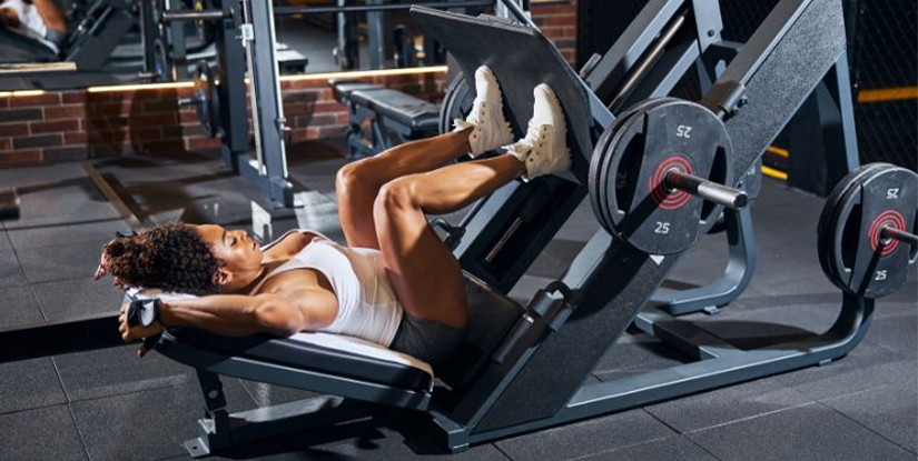
A common misconception in facility management is that safety is a static attribute determined at the moment of purchase. Many operators believe that once a piece of equipment is installed, its safety profile remains unchanged until a major failure occurs. However, from a technical engineering perspective, safety is a dynamic equilibrium between material integrity, mechanical tolerance, and rigorous maintenance protocols. When strength workout equipment fails, it is rarely a spontaneous event; it is typically the culmination of cumulative fatigue, inadequate lubrication, or unmonitored structural deformation.
The Structural Integrity of High-Load Frames
The primary defense against catastrophic failure in any weightlifting environment is the structural frame of the equipment. A misunderstanding of steel grades and welding techniques often leads operators to underestimate the long-term stability of their assets. To understand how strength workout equipment supports safe training, one must first analyze the fundamental skeletal components that bear the highest kinetic loads.
Material Selection and Wall Thickness Standards
The resistance to buckling and bending is primarily dictated by the steel gauge and the quality of the cold-rolled or hot-rolled steel used in production. In high-traffic commercial environments, the failure mode is often not the steel snapping, but the deformation of the tubing under repetitive load cycles. High-quality equipment utilizes thicker-walled steel tubing to ensure that the elastic deformation range is significantly higher than the expected operational loads.
Failure Mode Analysis: A common mistake is ignoring micro-deformations in vertical uprights. If a rack's upright begins to bow—even slightly—it indicates that the material has exceeded its elastic limit and entered the plastic deformation stage. Once this happens, the structural integrity is permanently compromised, and the equipment can no longer be considered safe for maximum effort lifts.
| Feature Component | Low-Grade Specification | Commercial-Grade Specification | Verification Method |
|---|---|---|---|
| Steel Wall Thickness | 11-gauge (approx. 3mm) | 7-gauge to 3-gauge (approx. 4mm+) | Digital Caliper Measurement |
| Welding Type | Standard MIG Welding | Full-Penetration TIG/MIG Hybrid | Visual Inspection for Porosity |
| Powder Coating | Thin/Standard Coating | High-Impact Electrostatic Finish | Scratch/Corrosion Check |
Understanding the rigidity of the frame provides the foundation for understanding more complex moving parts. As the structure stabilizes the load, the mechanical interfaces must then manage the movement.
Precision in Kinematics: Guide Rods and Bearing Systems
While the frame provides the static base, the actual training movement is governed by the precision of the kinematic systems—such as guide rods in a Smith machine or the bearing housings in a selectorized machine. The transition from static support to dynamic movement is where many mechanical failures originate, often due to friction-induced wear.
The Role of Surface Finish in Friction Reduction
The roughness of a guide rod is a critical technical parameter. A rod with a high surface roughness (Ra value) will inevitably create high friction, leading to heat buildup and premature wear of the polymer bushings or bearings. High-performance equipment utilizes chrome plating or specialized hardening processes to ensure a low-friction, high-durability surface.
Implementation Detail: Operators should monitor the 'smoothness' of a rep. If a user reports a 'stuttering' sensation during a movement, it is rarely a user error. It is often a sign of scoring on the guide rod or a collapsed bearing. The fix involves inspecting the rod for vertical scratches (scoring) and checking the bearing housing for excessive play.
- Step 1: Conduct a visual inspection of the rod surface under high-intensity light.
- Step 2: Feel the movement with a light load to detect vibration or 'catching.'
- Step 3: Verify the integrity of the polymer bushings for any melting or discoloration.
Once the smoothness of the movement is verified, the next critical area of focus is the integrity of the adjustable components that hold the weight.
Explore the complete technical specifications:
Adjustment Mechanisms and Load-Bearing Tolerances
Safe training relies heavily on the ability to adjust equipment to the individual user. However, the very mechanisms that allow for this flexibility—such as adjustment pins, pop-pins, and weight horns—are often the most vulnerable to mechanical fatigue. A single improperly seated pin can result in a complete failure of the vertical support system.
Verification of Pin Engagement and Locking Systems
A common failure in selectorized machines occurs when the weight pin is not fully seated in the selector rod. This creates an uneven distribution of weight, leading to lateral stress on the pin, which can eventually cause the pin to shear or the hole to elongate (ovaling). High-quality equipment mitigates this through the use of tapered pins and reinforced sleeve diameters.
Decision Criteria for Operators: When replacing or upgrading adjustment components, prioritize tapered pins over straight pins. Tapered pins naturally center themselves, ensuring that the load is distributed evenly across the diameter of the hole, which significantly extends the life of the adjustment mechanism.
To maintain these high-precision adjustment points, a rigorous lubrication and inspection schedule must be established, moving from the moving parts back to the structural foundations.
Explore the complete technical specifications:
Lubrication Protocols and Environmental Resistance
Mechanical components require more than just occasional attention; they require a technical approach to lubrication. Improper lubrication is just as dangerous as no lubrication, as certain lubricants can actually attract debris that acts as an abrasive, accelerating the wear of the very parts they were intended to protect.
Selecting the Correct Lubricant Type
Using a generic petroleum-based lubricant on a polymer bushing can lead to catastrophic failure. Petroleum can cause the polymer to swell or degrade, leading to a complete seizure of the moving parts. For guide rods, a dry-film lubricant or a specific silicone-based spray is often the required standard to prevent residue buildup.
| Component Type | Recommended Lubricant | Common Mistake | Frequency |
|---|---|---|---|
| Steel Guide Rods | Dry Silicone Spray | Using Heavy Grease (Attracts Dust) | Monthly |
| Chain/Cable Loops | Light Machine Oil | Using WD-40 (Evaporates Quickly) | Quarterly |
| Polymer Bushings | Dry Film Lubricant | Applying Petroleum Solvents | Bi-Annually |
Maintaining the correct lubrication state ensures that the mechanical tolerances discussed earlier remain within safe operating ranges. This leads us to the final, critical layer of defense: the cables and pulleys.
Cable Integrity and Pulley Alignment Systems
In almost all resistance-based training, the cable is the single most critical point of potential failure. A cable snap is an high-energy event that can cause immediate and severe injury. Understanding how strength workout equipment supports safe training requires a deep dive into the tension, fatigue, and alignment of these transmission systems.
Detection of Cable Fatigue and Fraying
Cables are subject to constant bending stress (fatigue) as they pass through pulleys. This creates a phenomenon known as 'wire breakage' or 'bird-caging,' where individual strands of the steel wire unravel. Even a single broken strand in a 7-strand cable significantly reduces the overall tensile strength of the system.
The 'Touch and Sight' Inspection Method:
1. The Sight Test: Run the cable through its entire range of motion. Look for any areas where the cable appears 'swollen' or where the inner core is visible.
2. The Tactile Test: Using a gloved hand, run your fingers along the length of the cable (while under light tension). Feel for any small, sharp protrusions. These are the broken strands that signal an imminent failure.
If a cable shows even a single broken strand, the decision-making protocol is absolute: the equipment must be tagged out of service immediately. There is no 'safe' threshold for a frayed cable.
Upholstery and Ergonomic Surface Maintenance
While often overlooked by technical analysts, the upholstery and contact surfaces of strength equipment are vital for both biomechanical safety and hygiene. A collapsed foam pad is not just a comfort issue; it is a safety issue that alters the user's center of gravity and alignment.
The Link Between Ergonomics and Injury Prevention
If a bench pad has lost its density, the lifter may experience an uncontrolled tilt during heavy lifts. This instability can lead to spinal misalignment or sudden shifts in weight that the equipment's frame was not intended to handle in an unbalanced state. Furthermore, cracked or torn upholstery can harbor bacteria and moisture, leading to material degradation.
Implementation Checklist for Upholstery:
- Density Check: Press firmly on the pad. If you can feel the structural board underneath easily, the foam has collapsed.
- Seam Integrity: Inspect all stitching for fraying or separation.
- Surface Integrity: Look for cracks in the vinyl that could allow sweat to penetrate the internal foam.
By ensuring the contact surfaces are intact, the operator protects the mechanical stability of the movement, completing the circle of safety from the frame to the user's contact point.
Operational Compliance and Documentation
A sophisticated safety culture is not built on a single inspection, but on a documented history of technical compliance. For facility operators, the final step in ensuring that strength workout equipment supports safe training is the creation of an immutable log of all maintenance and inspection activities.
The Role of a Formal Maintenance Log
A maintenance log serves as the technical 'black box' for the equipment. It should include the date of inspection, the specific component checked (e.g., 'Cable Tension' or 'Bolt Torque'), the action taken, and the signature of the technician. This documentation is essential for liability protection and for identifying long-term trends in equipment wear.
Example of a High-Standard Log Entry:
'Date: 2023-10-12 | Equipment: Leg Press Model X | Task: Bolt Torque Verification | Result: Tightened 4x base bolts to spec; No visible deformation noted | Technician: J. Doe'
When an organization moves from a reactive 'fix it when it breaks' model to a proactive 'verify it every month' model, the lifecycle of the equipment increases, and the risk profile decreases. This transition from maintenance as a chore to maintenance as an engineering discipline is the hallmark of a professional operation.