

How to Design a Strength Equipment Layout for Your Gym
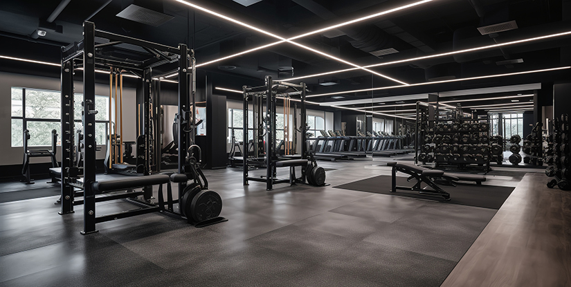
Optimizing Spatial Efficiency and Traffic Flow Patterns
A common failure in new facility design is the 'bottleneck effect,' where equipment is placed so densely that users cannot navigate safely during peak hours. This usually occurs when operators prioritize maximum piece counts over human movement. A poorly designed layout leads to increased injury risk, user frustration, and a perceived reduction in facility quality. To prevent this, a technical approach to floor planning must account for both the physical footprint of the machine and the dynamic 'operational envelope' required for safe use.
Defining the Operational Envelope
Every piece of strength equipment has two distinct dimensions: the static footprint and the operational envelope. The static footprint is the physical space the machine occupies on the floor. The operational envelope includes the maximum reach of the user, the trajectory of moving parts (such as weight stacks or rotating arms), and the clearance required for a person to approach and exit the machine. When designing the layout, you must use the larger of these two values to prevent collisions.
Standard Clearances for High-Traffic Zones
Failure to provide adequate clearance between rows of machines often leads to equipment damage and user collision. Operators should implement a structured clearance protocol based on the following categories:
| Equipment Type | Minimum Clearance (Static to Static) | Recommended User Path Width |
|---|---|---|
| Selectorized Machines | 0.6m - 0.9m | 1.2m |
| Free Weight Racks | 1.5m - 2.0m | 1.8m |
| Functional Training Racks | 2.0m + | 2.5m |
By establishing these minimum thresholds, you ensure that even during high-occupancy periods, the facility remains navigable. Once the macro-scale dimensions are established, the next critical step involves grouping equipment by mechanical and user-specific requirements.
Implementing Functional Zoning for Strength Modalities
Effective zoning is the process of grouping equipment based on movement patterns and user intent rather than just available floor space. A major mistake among novice operators is placing heavy barbell platforms adjacent to highly technical selectorized machines. The vibration and high-impact nature of heavy lifting can disturb the stability and precision of delicate cable machines, leading to premature wear on bushings and bearings.
Categorizing by Mechanical Profile
To optimize the floor, categorize your inventory into three distinct mechanical profiles. This ensures that high-vibration zones are isolated from high-precision zones.
- High-Impact Zones: Primarily for free weights, deadlift platforms, and bumper plate usage. These areas require reinforced flooring and significant vibration isolation.
- Dynamic Movement Zones: Includes functional trainers, cable crossovers, and kettlebell areas. These require open, unobstructed space to accommodate multi-planar movements.
- Controlled Resistance Zones: Focused on selectorized machines and fixed-path strength equipment. These are ideal for central placement where stability is a priority.
Verification of Zone Boundaries
To verify a successful zoning strategy, a facility manager should perform a 'stress test' by simulating a high-traffic hour. Observe if the sound or vibration from the high-impact zone affects the user experience in the controlled resistance area. If users are moving excessively to avoid vibration or noise, the zones are too closely integrated. Establishing these boundaries leads directly into the technical requirements of the equipment itself.
Managing Floor Load and Structural Integrity Requirements
A critical oversight in gym design is neglecting the structural capacity of the subfloor. Strength equipment, especially heavy deadlift platforms and large multi-station racks, exerts massive static and dynamic loads. If the floor's load-bearing capacity is underestimated, the facility may face structural cracks or subfloor subsidence over time.
Static vs. Dynamic Load Calculations
When designing the layout, you must differentiate between static load (the weight of the machine and the user) and dynamic load (the force generated during a heavy lift or a dropped weight). For example, a 100kg barbell dropped from a height creates a momentary impact force several times greater than 100kg. Ignoring this leads to accelerated wear on the floor's structural integrity.
Technical Checklist for Floor Verification
Before finalizing the layout, professional operators should verify the following parameters with their structural engineer:
- Point Load Capacity: Can the floor support the concentrated weight of a single heavy rack leg?
- Impact Absorption Requirements: Does the floor material meet the industry standards for shock absorption to protect the subfloor from dynamic forces?
- Subfloor Levelness: Is the floor sufficiently level (typically < 3mm deviation over 3m) to prevent machine wobbling?
Ensuring the floor can handle the load is just as important as the layout itself, as even a perfectly spaced machine will perform poorly on an uneven or weak surface. This structural stability provides the foundation for the safety of the equipment placement.
Explore the complete technical specifications:
How to Plan a Gym Layout That Maximizes Floor Space | Expert Guide
Standardizing Equipment Alignment and Maintenance Access
Even with a perfect floor and zone plan, a layout can fail if the individual machines are not aligned with technical precision. Improperly aligned equipment leads to uneven wear on the machine's internal parts, such as cables, pulleys, and guide rods, which in turn increases maintenance costs and reduces equipment lifespan.
The Importance of Axial Alignment
For machines involving cables and pulleys, the alignment of the weight stack relative to the load-bearing components is vital. If a machine is placed on a slight incline or an uneven floor, the cable will pull at an angle. This lateral tension causes premature fraying and increases friction within the pulley system. Operators must ensure that all heavy machines are level using a digital spirit level during the installation phase.
Maintenance Access Clearances
A common mistake is placing heavy machines against walls or too closely to one another, which prevents technicians from accessing the internal components. If a technician cannot reach the motor of a treadmill or the adjustment bolts of a weight stack, routine maintenance is skipped, leading to catastrophic failure.
| Component Requiring Access | Recommended Maintenance Clearance | Reason for Requirement |
|---|---|---|
| Selectorized Weight Stacks | 45cm - 60cm | Access to pins and weight plates |
| Treadmill Motors | 30cm - 45cm | Rear access for motor/control board |
| Cable Pulley Systems | 20cm - 30cm | Cable replacement and tensioning |
| Multi-Station Racks | 50cm + | Bolt tightening and frame inspection |
By documenting these clearance requirements in the initial design, you protect the long-term ROI of your equipment. Consistent maintenance access is the precursor to a reliable safety inspection routine.
Explore the complete technical specifications:
Power Lift Gym Equipment: Engineered for Strength Performance
Developing Rigorous Safety Protocols and Hazard Mitigation
Once the equipment is installed and aligned, the final layer of design involves the implementation of safety protocols. A layout is not truly complete until it accounts for the human element of error. Hazard mitigation in gym design focuses on preventing user-to-user and user-to-equipment collisions through physical barriers and psychological cues.
Designing for Visibility and Supervision
A common failure mode in large-scale gyms is the creation of 'blind spots.' These are areas where a user performing a complex or heavy lift (such as a back squat or a heavy pull) is not visible to staff or other users. A well-designed layout ensures that staff can monitor high-risk zones from various vantage points. This visibility is essential for rapid response during a medical emergency or a mechanical failure.
Implementing Visual and Physical Cues
To guide users through the layout safely, designers should use visual cues to define safe operating zones. This can include:
- Color-Coded Flooring: Using different colors to denote high-impact zones versus walking paths.
- Floor Markings: Taping or painting specific boundaries around heavy free-weight areas.
- Signage Placement: Ensuring that safety instructions and weight limits are placed at eye level for each specific piece of equipment.
Effective mitigation reduces the frequency of accidents and ensures that the layout works in harmony with the users' behaviors. This leads us to the final stage: the ongoing verification of the facility's operational standards.
Optimizing Lighting and Acoustic Environment Design
While mechanical layouts focus on machines, a complete strength environment must also account for sensory inputs. Poor lighting or excessive noise levels can distract users, leading to poor form and increased injury risk. When designing the layout, consider how electrical placement and ceiling height interact with the physical machines.
Lighting Placement and Shadow Prevention
A common mistake is placing bright overhead lights directly above high-intensity stations, such as power racks or benches. This can cause distracting glare or create harsh shadows that obscure a user's view of their own form. Instead, aim for diffused lighting that provides uniform coverage. For technical movements, ensure that light is positioned to illuminate the floor area without creating a blinding effect for the lifter.
Managing Acoustic Resonance
Strength training environments are inherently loud due to metal-on-metal contact and dropping weights. A failure to manage acoustics can lead to a high-stress environment. To mitigate this, consider the following parameters:
- Material Density: Use high-density rubber flooring to dampen the sound of free weights.
- Ceiling Height: In facilities with lower ceilings, sound can bounce aggressively. Integrating acoustic panels in the design can help break up these reflections.
By balancing the physical placement of equipment with the sensory requirements of the space, you create a professional atmosphere that supports long-term user retention.
Establishing a Verification and Continuous Improvement Cycle
Designing a layout is not a one-time task but a continuous process of verification. Even the most professional designs must evolve as the gym's membership demographics or equipment inventory changes. To maintain a high standard, operators must establish a systematic way to audit the layout's performance.
The Audit Framework
A professional facility manager should conduct a quarterly audit of the floor layout to identify any emerging issues. This audit should focus on three primary metrics: movement friction, equipment wear, and user feedback. If users frequently report that certain areas feel 'crowded' or 'unsafe,' the layout needs re-evaluation.
Common Indicators of Layout Failure
Operators should watch for these technical indicators that suggest the layout needs adjustment:
- Accelerated Cable Fraying: Suggests poor axial alignment or excessive tension due to floor unevenness.
- Floor Scuffing in High-Traffic Areas: Indicates that the walking paths are not wide enough or are poorly placed.
- Increased Maintenance Requests: Often a sign that machines are placed in areas with poor access or excessive vibration.
By treating the layout as a living technical system, you ensure that the facility remains a high-performing environment for years to come.