

Optimizing Facility Workflow: What a Gym Floor Plan Equipment Layout Includes
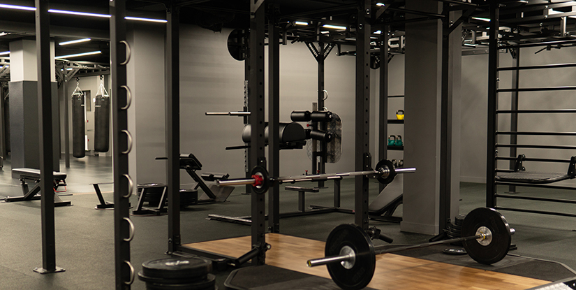
Beyond Aesthetic Placement: The Structural Logic of Layouts
Many facility operators mistakenly assume that a gym floor plan is simply a matter of placing machines where they look visually symmetrical. This aesthetic-first approach often leads to operational bottlenecks, such as high-traffic friction points or unsafe distances between heavy lifting stations. A professional equipment layout is a complex engineering solution that must account for human biomechanics, machine footprint, and mechanical clearance. By prioritizing functional zones over visual symmetry, operators can ensure long-term durability of both the equipment and the facility's operational flow.
A common failure occurs when a facility manager overlooks the 'swept volume'—the total space a piece of equipment occupies during its full range of motion. If a cable machine is placed too close to a stationary bike, a user's momentum might cause a collision. Understanding these dimensional realities is the first step toward a high-performance layout. This foundational understanding leads directly into the specific technical components that must be documented in a comprehensive plan.
The Cost of Poor Spatial Calculation
When spatial margins are ignored, the result is not just an awkward room, but increased liability and accelerated wear. Weaker layout strategies typically suffer from:
- Equipment Interference: Collision between moving parts and stationary objects.
- Navigation Obstruction: Blocked pathways for emergency egress and cleaning crews.
- Ergonomic Friction: Users feeling cramped, which reduces the perceived value of the facility.
The Core Components of a Functional Equipment Layout
Building on the necessity of spatial logic, a professional plan must categorize equipment into distinct functional zones. Each zone has unique requirements regarding floor loading, power access, and ventilation. A haphazard mix of zones creates a 'chaos factor' where a user transitioning from cardio to strength training finds the path obstructed or illogical.
A robust layout includes a detailed zoning map that separates high-impact areas from low-impact ones. For instance, a free weight section requires significantly more floor thickness and sound attenuation than a functional training area. Below is a breakdown of how different zones are typically categorized in a professional specification document.
| Zone Type | Primary Equipment Examples | Technical Requirements | Typical Floor Material |
|---|---|---|---|
| Cardiovascular Zone | Treadmills, Ellipticals, Rowers | Dedicated electrical circuits, HVAC airflow | Low-pile carpet or rubber tiles |
| Strength Training Zone | Smith Machines, Power Racks, Benches | High impact resistance, heavy load bearing | High-density vulcanized rubber |
| Functional/Mobility Area | Kettlebells, TRX, Medicine Balls | Open floor space, non-slip surfaces | Multi-density foam or turf |
| Selectorized Machine Area | Cable machines, Leg press, Chest press | Standard clearance, electrical proximity | Standard commercial rubber |
By categorizing equipment this way, the operator can allocate resources more effectively. For example, the Cardiovascular Zone requires an emphasis on electrical infrastructure, whereas the Strength Training Zone focuses on structural load. Identifying these needs prevents the common mistake of purchasing equipment that the existing facility cannot support. After defining the zones, the next critical step is calculating the specific clearances required for safety.
Safety Clearances and Human Biomechanics
A professional gym floor plan equipment layout includes rigorous safety buffer calculations. It is not enough to know the dimensions of the machine itself; one must know the 'operational footprint.' This includes the space required for a user to step onto a treadmill, the length of a barbell during a deadlift, and the swing radius of a kettlebell.
Calculating the Operational Footprint
To avoid the failure mode of equipment collision, designers must use the following checklist when verifying machine spacing:
- The Maximum Extension Rule: Measure the longest possible reach of a cable or moving part.
- The User Interaction Margin: Add a minimum of 30-45cm around all entry/exit points of a machine.
- The Barbell Path Radius: For free weights, calculate the arc of a weight plate rotation to prevent floor damage.
- The Walking Path Minimum: Ensure major thoroughfares maintain a minimum width of 120cm for safety and accessibility.
If these margins are ignored, the facility risks high turnover rates as users find the environment frustrating or even dangerous. A properly calculated buffer ensures that the movement of one client does not impede the training of another. Once the safety boundaries are established, the plan must transition into the technical installation requirements, specifically focusing on electrical and structural integration.
Explore the complete technical specifications:
How to Plan a Gym Layout That Maximizes Floor Space | Expert Guide
Technical Infrastructure and Utility Integration
A common mistake in gym design is treating the floor plan as a static image. In reality, a layout is a blueprint for a complex utility network. A high-performance plan must integrate the mechanical needs of the machines with the building's existing or planned infrastructure.
Failure to plan for utility placement often results in 'cable spaghetti'—hazardous loose wires running across walking paths—or machines that cannot be powered. This is especially critical in modern facilities where high-tech cardio equipment requires constant connectivity and stable power. The following table outlines the technical integration points that must be cross-referenced with the floor plan.
| Utility Type | Implementation Detail | Common Failure Mode | Verification Method |
|---|---|---|---|
| Electrical Power | Dedicated circuits for cardio/selectorized | Tripped breakers due to peak load | Load calculation vs. circuit capacity |
| Data/Connectivity | Ethernet or stable Wi-Fi zones | Unstable software/updates on machines | Signal strength testing in all zones |
| Floor Loading | Structural support for free weight areas | Subfloor damage/cracking | Engineering load-bearing certification |
| HVAC/Airflow | Vents positioned for machine heat dissipation | Hot spots in cardio zones | Airflow velocity measurement |
By verifying these technical points during the design phase, operators avoid the downtime caused by improper power or connectivity. With the technical infrastructure secured, the focus shifts to the long-term upkeep of the layout through systematic maintenance and inspection.
Explore the complete technical specifications:
Routine Maintenance and Layout Longevity
The stability of an equipment layout is not permanent; it is subject to the stresses of daily use and the environmental factors of the facility. A professional operator recognizes that the floor plan is a living document that requires regular inspection to ensure the physical layout remains safe and efficient.
Over time, heavy equipment can settle or shift, potentially compromising the safety clearances calculated during the initial setup. For instance, a heavy power rack may slightly sink into the rubber flooring, altering its levelness and affecting its stability. Regular audits are required to maintain the integrity of the original design.
The Facility Operator’s Inspection Checklist
To ensure the layout remains compliant with the original safety standards, operators should perform the following checks quarterly:
- Footprint Verification: Re-measure distances between heavy machines to ensure no 'creep' has occurred.
- Floor Integrity Audit: Inspect rubber tiles for lifting, cracks, or unevenness that could create trip hazards.
- Clearance Obstruction Check: Ensure no new, non-compliant equipment (like small accessories) has been placed in high-traffic thoroughfares.
- Cable & Cord Management: Check that all power cords and data cables remain tucked and secured within their designated channels.
A consistent maintenance cadence prevents minor issues from becoming major liabilities. As the physical facility ages, the operator must also remain aware of how the layout can be updated or optimized to meet changing market demands.
Weight Distribution and Floor Load Capacity
One of the most overlooked aspects of what a gym floor plan equipment layout includes is the sheer weight of the mechanical loads. While a standard commercial building might support general office weight, a gym with heavy free weights and high-impact machines requires specialized structural scrutiny. A common failure mode is the gradual sinking or cracking of the subfloor due to localized high-pressure points.
When placing heavy machines, you must distinguish between 'static weight' (the weight of the machine itself) and 'dynamic weight' (the force applied when a user drops a barbell or jumps on a treadmill). To prevent structural failure, consider the following load density parameters:
- Point Loading: High-intensity areas like power racks require reinforcement or thicker, high-density mats to distribute weight across a wider area.
- Vibration Dampening: High-impact zones (plyometrics or heavy cardio) require materials that absorb kinetic energy to prevent structural resonance through the building.
- Subfloor Leveling: Even a 1-degree tilt in a subfloor can lead to significant mechanical wear on heavy treadmills over time.
Properly accounting for these loads ensures the long-term integrity of your building. Once the heavy-duty structural requirements are addressed, the focus shifts to the long-term evolution of the space.
Future-Proofing and Iterative Layout Optimization
A mistake often made by new facility owners is creating a rigid layout that cannot adapt to changing fitness trends. A gym that only provides heavy free weights might struggle if the market shifts toward functional training or specialized recovery zones. Therefore, a professional plan includes an 'expansion and adaptation' strategy.
Future-proofing means designing the floor plan with modularity in mind. This involves choosing flooring that is easy to replace in sections and ensuring that electrical and data points are accessible but not permanent fixtures. A modular approach allows the operator to pivot the facility's focus without a total overhaul. When planning for the future, consider the following decision criteria:
- Scalability: Can you add 15% more equipment to this zone without violating safety margins?
- Modular Utility: Are power outlets movable or easily extended via surface-mounted conduits?
- Floor Versatility: Is the base floor material capable of supporting a secondary layer (e.g., turf over rubber) if a new zone is needed?
By building these considerations into the initial layout, the operator secures a higher return on investment (ROI) and ensures the facility remains relevant. Ultimately, a well-executed gym floor plan is a balance of engineering, safety, and long-term operational foresight.